The Workbench

The Workbench
Making my Dreams a Reality

Wednesday, October 7, 2009

Solar Power, Competitions, and Rats

Hey Guys,

Been a long time since I last posted. I had been bsy for a while, and then forgot to post...

On with the show!

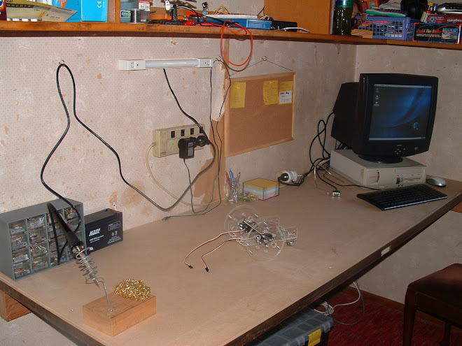
First a picture of my workbench (before I gave it a quick tidy):


Been busy as you can tell!

I've been tinkering with some cheap solar lights to make a node for my data logger. I wanted a self-sufficient wireless sensor - and so it was born. I've been asking about solar power on the PICAXE forum, and somebody has suggested that with a duty cycle like mine (0.041%) that I use a super capacitor... Currently I have a bulky battery pack made up of four 2500mAh NiMh AA cells. A super capacitor will be much much smaller, and will still have the current push I need. So long as it has the required capacitance to allow for about 50mA to be drawn for about 1.5s every one or two hours (1.23mA average versus 0.6mA average).


The two cells are wired in series, and can provide an open circuit voltage of about 6.3v, and a short circuit current of about 35mA. If these are enough to charge the batteries, then it is going to have plenty of juice to power my device. Overkill if you ask me... I'll make sure to increase the duty cycle to make use of extra energy. No use wasting it!


Science fair. I won big! I've ended up with $485 cash all up. First we had the school science fair, I gained automatic entry into the BOP regional finals as I was the only senior entry with my "microLOG" system. Next came the big day - too fast if you ask me! Dad and I drove to Rotorua, and I spent the day telling judges about my project. I talked to maybe 5 - 6 sets of judges (needed a drink real bad!). The next day I went along to prize-giving, and won four different awards - 1st for the IPENZ Engineering Award, 1st in Senior Technology, 1st in Radio Science, and I won a nomination for - the New Zealand National Science Fair. I was stunned! I won $450, an nomination for realise the dream, and I won a HAM radio receiver for 12 months!


I've built a half-wave dipole antenna for the 40 meter band. Works great! Lately I haven't had a chance to listen, as I have no ground, and the antenna has been temporarily cut down...


Mum has gone rat mental, and adopted another two rats. Whiskers and Bundles. Whiskers is white with a brown hood, and spots. Bundles looks the same as Delilah except a little darker, and a little bigger. After a week and a it in separate cages to avoid fights, they have all moved into the one cage. No major fights, so it seems everything has settled nicely.

Whiskers:


Bundles (and Lilli):


That was a quick post on what I've been up to. Most of the work has gone into this:


and


I'll post again (eventually :-P)

MM171

Sunday, May 24, 2009

Almost a month.

Hello readers!

Been almost a month since my last post! I've been sick for a while, and school, homework... I get busy. After looking at other people's blogs, a couple of posts per month is fairly average...

So what's on the bench?

I have managed to get my RTC reading and writing. All I need now is a clock crystal and it will actually oscillate. That means it will tick over. It was much easier than I thought, I had been putting it off for a long time xD.

The wireless units are packing a sad, so I haven't gotten very far with those. I have however made the design up for the temperature transmitter. That also was easier than I thought.


For the datalogger I have designed a system for back up battery power. It's not interfaced with the PICAXE yet, but you can expect that to happen soon =). It works by having a relay witched by 12v. The N/C side of the relay is wired to the battery. So when there is 12v, (mains plug pack), the relay OPENS this side. Therefore disconnecting the battery. When the plugpack is disconnected, the relay ticks over and the unit is then powered by battery. The PICAXE will be able to sense this, and be able to switch to a lowered power state, (maybe). All of this depends on the model of unit. You know in the shops you have tons of units to choose from? This too will have many possibilities, and I am trying to be as modular as possible. That way it is just a matter of plugging in the correct modules.

I love to keep moving, so when I hit a block it is hard to stay focused. I am trying REALLY had to stay on track, so I follow a to-do list. I have to fix the wireless units, that involves getting a fresh set. I need to get a crystal for the RTC, that is now on order. I am ditching the casio interface, and will resort to a FREE serial communications program coupled with excel (not free, but most if not all schools have it...).

I think I will add an LCD module to the device, that way it is possible to see what's going on.

The aim is to stay waterproof, so lockable lunch boxes will be used. The LCD will have a clear window to look through. Even if I don't have the unit outdoors, it will still be possible to do so.


What else is on the bench? Surely more than just the datalogger! You would be right there, I am also making a two dice electronic dice with traditional display. Yup, this bad boy will have two dice. All controlled by ONE PICAXE 08M. The 08M has 4 OP pins. Three of them can be used as tri-state. I am using two tristate pins to control the dice displays, and a plain old OP pin to switch a transistor to select the dice being displayed. The wireing was easy. The code? Not so much... I am trying to find a way of having the PICAXE generate two random numbers, choose which dice number the corrosponds too, and then display that number on the dice. It will have to flash really quickly between the two dice to show two different numbers (seemingly as the same time!). This is due to Persistance of Vision, a phenomenom where the brain updates your vision slower than what is bing updated, so you see both dice at the same time.


My windmill. I have chosen a savonius design this time. Due to renovations, this one is going on the shelf for a little while. You heard right, renovations. Or house is having an overhaul! New Ensuite, new bathroom, sister gets a new room, Dad and I get a new garage! It's going to be good =). Construction commenses on the 1st of June (day after queen's birthday weekend). We have a shipping container on the front lawn to hold our stuff. The go kart, the windmill, and more have going in here.


I guess I'll make another post soon, I'm busier in the holidays normally. So I would normally make more posts then, but I forget =).

Bye,

Dan!

Monday, April 27, 2009

So what's been happening on the bench?

Been a while, these holidays haven't lent themselves to getting anything done.

Now the holidays are over, I have started doing stuff again, getting back into the swing of things.

So what have I done on everything...? Let me see, I have started building a CNC machine, Wired up the Go Kart, Built a wireless pair, Found a F&P Smart Drive motor, Updated to Ubuntu 9.04 (AKA Jaunty Jackalope), Build a water rocket launcher.

All that in one set of holidays :-O.

Sitting on my bench right now I have this:


This is the entire go kart electrics system. I also have a multimeter hooked up to read the temperature (max to date is 55°C). I got the battery pictured and another one, (same type), for free off a wrecker in Tirau. What I need to do is de-sulfate it. This involves building a circuit designed to de-sulfate. I will get around to it... The driver along with the MOSFETs does exactly as it should, and I am very pleased. The main problem at the moment is, because the battery is so old and crappy, I can stop the motor shaft with my bare hand. If I can stop it, so can the weight of the go kart right? After de-sufating the battery, it will be able to hold much more charge.

I mentioned earlier about the CNC machine. My dad saw the IT department of #####, (place of work), was having a MAJOR clean out. I scored a computer power supply (which is now dead due to unknown causes), 2 dot matrix printers, 2 scanners, 2 USB keyboards, a UPS, (Uninterruptible Power Supply), and two gigaset network phones (Can be made into walkie talkies).

Back to the CNC machine, inside the printers and scanners there were stepper motors, these stepper motors can be "stepped" by a computer. Each step is a few degrees. I have ordered some H-Bridge chips from ST Micro to control each motor (3 in total). I also realized I will need a controller for each stepper. The program I will use to control the CNC machine is called Mach3. This program has two wires per motor on the parallel port - step and direction. I will need to create an interface so the four inputs for the H-Bridge can be controlled by the two output pins on the parallel port. I have already found the driver, just a matter of building it.

I have built a new PIC Programmer, (maybe a PIC can be used for the driver...), same as all previous attempts. It is a JDM style progrmmer built onto a Kiwi Patch board from Andrew.


I haven't tested this yet as I have to revert to windows. I know there are linux programmers out there, but I really like icprog. Maybe WINE can be used instead.

Whats happening with the smart drive motor?


I will tell you. It has been rewired for 12v operation, and is currently being "decogged". This means I file each pole, (46 in total), into a nice curved shape. This will improve performance in low wind. I also have to build a new set of blades to drive the thing, it's much "chunkier" than all predecessors. Wood seems to be the best bet, but that will take a long tie, and I don't think I have all the tools to build them. So... Maybe I will have to give the PVC blades a try. I can cannibalize them from the six blade windmill.

Another project, yes another one! I am getting back into water rockets. After being inspired by George Katz from Air Command in Aussie. I have built the "Gardena" launcher, only I used a cheap aluminium socket from The Warehouse. The nozzles on these rockets are 9mm, giving more "burn time" than my older rockets (nozzle size of about 19mm).


Deal Extreme sells cheap Chinese crap. I found a nice cheap servo motor than will do the job nicely. By job I mean deploy the parachute. I have build a launch computer built onto a PICAXE 08M capable of pulling the pin on the parachute door. Previously I used the NSA, (Nose Seperates at Apogee), and this just sucked... I only ever had one success.

It was the greatest success of all time! There was a holiday program running at the park at the end of my street. All the kids had seen a couple of my launches, (failed parachutes), and decided to come outsude and sit down to watch. It was going to be my last shot of the day. I charged it up, pulled the string, and hoped for the best. To my surprise, and the the kids awe, the parachute deployed. It was absoloutely awesome to have such a big audience cheering away at something you yourself were amazed at.

Anyway, back to the computer. This computer detects launch, waits a short time, and then pulls the pin. This should be MUCH more reliable than old NSA...


Pictured is Version 1.1 Beta. I am currently at 1.2 Beta. Please note, the rocket has not yet left the ground.

Here is 1.0 Alpha:


In the real version, I do use the nokia battery. I have three old nokia phones, with batteries! I have used one here, one is on my bench, and one still powers a phone. I have soldered a jack onto the computer so you can recharge.

Wow, that was a lot to type. Guess that's what happens when you are as busy as me, and are too lazy to blog about it!

Hope you enjoyed reading =)

Dan

Thursday, April 9, 2009

Go Kart Controller


I have finished the hardware for the Go Kart Controller. It consists of the potentiometer, (for pedal location detection), the MOSFET array, (for switching), and the PICAXE, (the brain).

I haven't yet finished the code for the PICAXE. The program will monitor the resistance of the potentiometer. When the resistance rises, the motor will accelerate/decelerate and vice versa. To change the speed of the motor I will used PWM on the MOSFETs. I have tested this with an LED and it works just fine. The PWM in this case is at 10,000Hz. This means the circuit is switching on and off 10,000 times a second! The duty cycle is determined by the potentiometer.


These four MOSFETs are IRF1405. According to their data sheet they are capable of about 100A at about 100°C. Having four of them wired in parallel means I can have 400A at 100°C. Most sites I've been on state that starter motor current peaks at about 300A. 400A should be plenty enough!


Not much news on the data logger just yet. Bought some more parts of Andrew (wireless units!). I have NO idea how to get the Casio working... I've done it before, but it doesn't want to work just yet.

Sunday, April 5, 2009

All in a Day's Work


Today I did quite a bit on the go kart, not much on anything else. I tidied the bench just this morning. Look at it now!

Anyway, today I, with the help of my Dad :), re-did the case. I was hooking it up to the circuit, and the switch just kinda died... Bought NARVA brand gear. This stuff should last for years :-)

Before:


After:


Much better huh? The weird texture was caused after a failed polishing. The dremel, (even though it was a cloth pad), really dug in. Polishing compound was stronger than I though.

Also on the bench is the datalogger, haven't made ANY progress... Tried to hook up the calculator to 28X1, harder than it was first time around I can tell you!

In The Future...
Hopefully my part, (RTC), from wherever in the world it's coming from arrives soon. I'm also waiting for the four MOSFETs from Ross. He had to order them in from Jaycar, so I'm not too surprised it's taken a little while. Sick with some weird illness ATM, so I'll get a bit of progress on this project while I'm home. Was hoping to buy Crysis, but I'm not keen on leaving town... Would have been good though :-). My Dad is pretty keen on it, so I'm sure we'll get it soon.

Enough from me for this post. I'll write another post when stuff strats arriving :-)

Thursday, April 2, 2009

Quick Update

[NEWS]

The board will fit just fine. I was planning to buy it this weekend, and decided not to due to size limitations, but this box it over kill :-).

Just so you know, this box is on clearance, so is cheaper to buy this than the size down (about $3 less).

The Electrical Update

Data Logger:

I have, (as you know), ordered the Real Time Clock chip, and a few parts from Andrew H. Yesterday the coin cell, and the coin cell holder arrived from Andrew. I was so excited I didn't want to wait for the RTC from wherever in the world it's coming from, so I built the circuit all ready for the chip to be plugged in.


The clock carrier board can bee seen on the left, next to the 28X1 main board. The red wires lead to the socket for the casio lead. I haven't figured out how to do it yet, but I will. It involves some careful timing.


Go Kart Motor Driver

Was off sick from school today, (Gastroenteritis the Doc thinks), and priced up the bits and pieces I need for the enclosure. I'm planning to use a sealed polycarbonate project box. It has an IR68 rating, meaning that is is 100% dust proof, and Waterproof below 10m. I don't need it to be this good, but it will be good to have protection from the weather.

Anyway, the total cost of the parts comes to $34 from Jaycar, and $21 from DSE. I still have a $20 Gift Voucher for DSE from August last year! It's easy to see where I'll be buying the parts from. The problem is, you can't buy the case until AFTER you build the circuit. I'm not going to buy the case only to find nothing fits now am I...

The circuit will be build onto one of the KiwiPatch boards from Andrew. He has a great deal where you can get one free for every picture you post of one with a project. I have, let me count), six boards. I haven't claimed many of them either, (three in fact), so it won't be hard to increase my collection as needed. After this post I plan to measure the size of the board and compare it to the dimensions of the box. Fingers crossed.


More news next post :-)

Rats!

Me and my sister recently bought a pet rat each. I named mine Samantha, and Sarah named hers Lilly. We have just finished building them a new cage out of two run-of-the-mill pet store cages. It involved removing the top of one, the bottom of another, and cable tie-ing them together.


For two rats, I think the cage is PLENTY big enough!

Jack also bought Rats, so if ours, (or his), need somewhere to stay, we have it covered.


Mum absolutely adores these two, and can often be found either; With the Rats, making something for the Rats, or on the best Rat site on the net (The Dapper Rat). Just today she made them a sleeping bag from a fleece blanket, and an old towel. Thanks Mum :-)

Tuesday, March 24, 2009

Temperature and Copper Forming

Datalogger


I have installed the temperature sensors, and have wired them to the same box. This box will contain the PICAXE and the RF transmitter. I have sensors measuring; Inside Temp, Outside Temp, Roof Cavity Temp, Exterior Wall temp (Measured from inside wall).


Go Kart


Took a LONG time to solder the wire... The cable is 8 gauge, and is made from the smaller copper fibers (like the ones you find in hook up wire). Should be a really strong connection :-). This cable is what I will use to hook to starter motor to the positive of the battery.

I have ordered the MOSFETs needed to make the switch, and I am waiting on the batteries, and the HUGE blocking diode (25ish Amps!!). To be honest, I don;t think I need one so big, but if I'm wrong, there goes $20 worth of MOSFETs...

Sunday, March 22, 2009

Been Busy Lately

Hey Guys,

I haven't made much progress on the Go Kart or the Datalogger...

Me and my sister have bought a pet rat each, and I have spent my time looking after Samantha. My friend Jack, Sarah (sister), and myself spent last weekend bulding them cages ($60 for a commercial one!). Haven't taken any pictures of them yet as I haven't got around to it just yet, but don't worry :-).


Go kart:

Tomorrow I will order 4x The needed MOSFETs. The switching power will be about 500A at 12V (6000W!!). Then I need to go to DSE and buy a meter of 8 gauge wire (1 meter Red 1 meter Black).


Datalogger:

Have ordered a RTC from maxim, and that should arrive in the next couple of weeks. I have also started to run the wires for the temperature sensors. Will measure; Roof Cavity, Inside, Outside and Inside the wall (touching the exterior wall). I am waiting for a meating with a man by the name of Dave. He has a fisher and paykel washing machine I may be able to have. I'm hoping it is a smart drive - they make good windmills. I also want to put up a new tower for the windmill so it gets a nice strong wind. I will have to follow some plans from a man in NZ - I can weld, and I can get scrap steel. Hoping wood is cheap, need about 5m!!. I dont think I can build a new tower, dad wouldn't be too pleased, (and just quietly I can't afford it :-P).


I would say that is enough from me for now.

Bye,

Dan - AKA Microman171

Saturday, March 14, 2009

The Go Kart


Me and my friend Jack are currently building a go kart.

It WAS going to be a petrol one, and I even bought the engine, but it didn't really work out... The engine was really old and damn hard to start.

So...

I now have a starter motor from some car.


I don't know anything about it, except that it runs on 12v.

Hopefully I will be able to get a couple of crappy old batteries from the wreckers I got the motor from.


This is the schematic for the PWM motor controller:


The four MOSFETs are going to be changed into 5. May seem excessive, especially when they are rated at 169A each! But they are only little TO 220 packages, and I don't know how much power they can dissipate. They are, however, quite happy running at about 70°C.

I am getting these MASSIVELY rated MOSFETs from Ross at Bright Sparks for $4.50 each - Thanks Ross!

Jack and I have just finished putting the Battery supports on. It is long enough to hold 3 - 4 batteries | || || | <-- Like that. I welded some angle iron onto one side, and the other side alreay had a bar. I used aluminium diamond plate for the actual support, and that it supported by another angle iron bar. It is all nicely bolted down.


Will keep posting updates as they come! Should be another one either this weekend or next. Getting the accelerator pedal hooked up to the potentiometer should be a bit of a challenge...

Will put everything into nice boxes :-). Due the the fact this kart is electric, I can have reverse too! It involves a single relay...!

Wednesday, March 11, 2009

First Post


I guess this will either work or it wont...

This will be where I can put some of my thoughts up onto the web. Was looking through the family blog I set up back in 2006, didn't work out... Was cool to see what I got up to. Just deleted it actually...

Any Way...


Lately I have been working on my Bright Sparks Competition Entry; The PICAXE based data logger. Plan A was to make it interface with a graphics calculator (Casio FX 9750G PLUS). Plan B is to have it interface with a computer and have that upload inot a spreadsheet.

Windows - hate it! If I was to go with plan B I would have to spend MUCH more time on windows. As if my gaming wasn't enough. I would say that a coupla hours on windows is an eternity - but I digress.

Plan B would have MUCH more memory than Plan A.

Plan A would involve wiring the PICAXE main board, (consisting of a 28X1 chip), to a 32K EEPROM. This EEPROM would store all of the sensor's variables with their time.

Real Time Clock - AKA RTC. I need a RTC of somekind so the 28X1 doesn't have to count, (which it is CRAP at!). This RTC would be read by the 28X1 whenever serial data was sent over the wireless network, (of my smaller 08M chips with sensors).

To put it simply:
28X1 = Main Board
08M = Sensor Board

The 08M transmits data (the variable\s) the the 28X1. The 28X1 read the data and stores it into its own variable\s. Then it would read the time from the RTC. The time and the variable\s would be stored as ONE variable in the EEPROM.

When the user wants to collect the data, he\she pulls out their casio calculator and plugs it up. They flick a switch on the 28X1 box. This activates CASIO mode. When the 28X1 is in CASIO mode, it no longer listens to the sensors. It will wait until the casio begins to ask for data. The 28X1 will begin the, (possibly slow), process of transmitting the variables (with time) to the casio. The casio will store it in a statistical list.

Actually... What if I didnt store the time and data together. That would make it easier right? That was I could transmit the time into list one, and the various data into differant lists. I can tell the casio is going to have a REALLY complicated program.

This is why I have my plan B. If I can get the whole system set up for CASIO mode, maybe I can convert that to COMPUTER mode. In COMPUTER mode, the 28X1 would be plugged up to the serial cable. The computer would begin, (the most likely quick), reieving of data. The data would be stored into a table, (maybe I can write a python App to put it into the linux equivilant of excel...).

We all know that all schools have excel (schools are my target audience). So they could hook the module up to the computer and get all of the data out of the EEPROM. Excel is very capable of graphing data (into a single graph!).

Plan B Subplan B would be to have the 28X1 ALWAYS hooked up to the computer. That removes the need for; a battery for the 28X1, an EEPROM, and an RTC.


I would say that is all I can really say about my bright sparks project (also will be my science fair project).

Next post will include pictures of this thing coming together!

Bye,

Dan